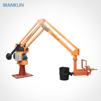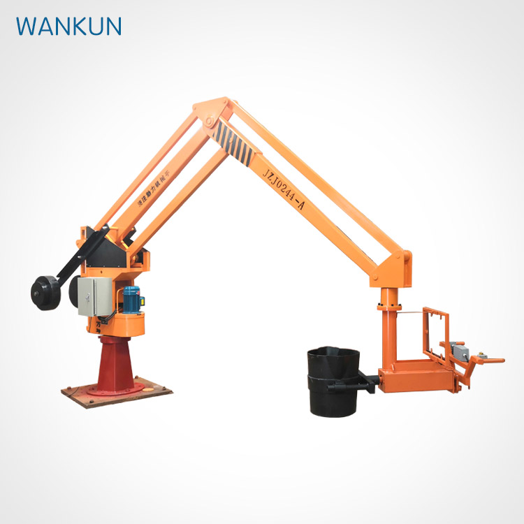
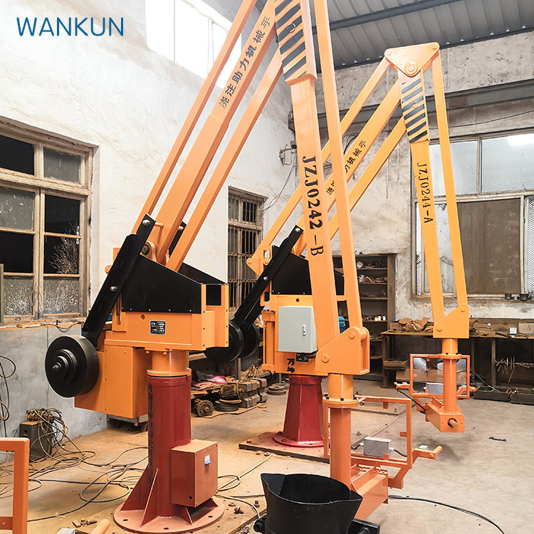
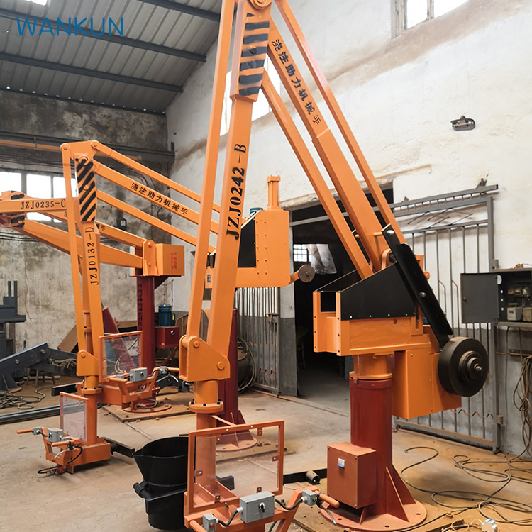
ZJZ series hydraulic casting manipulator
ZJZ series hydraulic casting manipulator is a new type of casting and lifting equipment, no travel switch, using the cylinder's own travel limit, and a buffer device. By the piston rod movement up and down to drive the lifting boom movement, the movement is relatively stable.
Product Description
ZJZ series hydraulic casting manipulator is a new type of casting and lifting equipment, with the following characteristics:
1, no travel switch, using the cylinder's own travel limit, and a buffer device. By the piston rod movement up and down to drive the lifting boom movement, the movement is relatively stable.
2. The hydraulic system is equipped with a safety device, which has a safety protection function in the case of overload and so on, and avoids the damage of the parts and accidents of the balance crane.
3. Zjz-s series pouring manipulator is equipped with speed limiting and self-lowering functions, which can make the weight drop more smoothly and save energy consumption. The MANIPULATOR IS SUITABLE FOR HIGH EFFICIENCY LIFTING AND ACCURATE POSITIONING AND installation of HEAVY objects within 300 kg, especially for medium and small FOUNdries. It has the advantages of small size, low noise, light weight, novel and compact structure, safe and reliable operation, simple and convenient maintenance, etc. It is a new product that liberates the operator from the manual labor of frequent loading and unloading and improves the production efficiency.
Hydraulic casting manipulator lifting heavy objects is achieved through the following three kinds of motion synthesis:
1, vertical lifting a hydraulic movement
2. Turn around the fuselage manually
3. Move horizontally manually
Main technical parameters of ZJZ hydraulic pouring manipulator
Table 1:
Model | ||||||||
0135 | 0235 | 0335 | 0140 | 0240 | 0340 | |||
Rated lifting weight(kg) | 100 | 200 | 300 | 100 | 200 | 300 | ||
Maximum operating radius(mm) | 3500 | 4000 | ||||||
Maximum lifting height(mm) | 1100,1300 Or custom | |||||||
Angle of rotation (degrees)
| 345 | |||||||
Motor | Model | Y90S-4 | ||||||
Rated speed | 1400 | |||||||
Rated power(kw) | 1.5 | |||||||
Oil viscosity (mm2/s) | The cleanliness of oil and system shall not be lower than GBT 14039-93 grade 19/16 or NAS 1638 grade 10 | |||||||
Specifications Number of anchor screws | M24x600x6 (Uniform distribution) | |||||||
Diameter of center circle of anchor screw D(mm) | 600 | |||||||
Recommended cement base size (length x width x depth) | 1000x1000x450 | 1000x1000x500 | 1250x1250x 600 | |||||
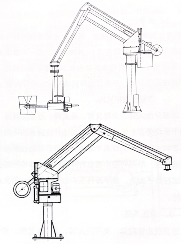
Outside drawing
Structure and principle
JZJ series hydraulic casting manipulator is composed of five parts: fuselage, balanced four-rod mechanism, hydraulic system and electrical control, pouring bag turnover device.
1. Fuselage:
This part consists of the base,
Rotating shaft seat, arm seat, vertical guide assembly, etc. The base can be set on a cement base (fixed) (see Table - for base dimensions) or fixed on a mobile cart (mobile). The body can rotate in the range of 345 degrees around the rotating shaft seat. The vertical guide assembly is fixed at the rear of the body, and the guide wheel of the balanced four-link mechanism moves up and down the guide groove.
2, balance four connecting rod mechanism:
This part is composed of large arm, large arm complex arm, lifting arm, lifting arm complex arm, connecting rod, support plate and balance block and other parts. The two sides of the hinge point between the support plate and the connecting rod are horizontally moved by a pair of single-row ball bearings on the guide rail of the body. The rear end of the large arm is connected with the head of the piston rod of the hydraulic cylinder through the nut, and the vertical movement is made along the guide groove. The adjusted balance block is installed on the big arm connected with four links, which is balanced with the self-weight of the balance rod, so that the spreader can achieve the purpose of casual balance.
3. Hydraulic system:
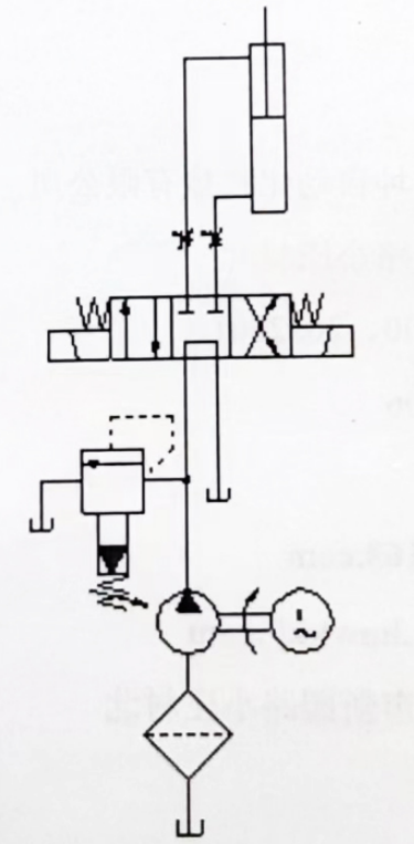
The system consists of gear pump, electromagnetic directional valve, inlet and return oil pipeline, safety valve, hydraulic cylinder and so on. When the operator press, rise (or fall) button, hydraulic oil through the electromagnetic valve into the cylinder, the lower chamber, push the piston rod down (or up) movement, through the four link lever principle, so as to drive the lifting movement of heavy objects. The speed of PLC series can be stepless speed regulation.
When the LIFTING weight EXCEEDS 1.1 times OF the rated weight, the safety valve is opened and unloaded, so that the weight can not be lifted, so as to protect the safety of the whole hydraulic balance crane. (See Figure 4 for the principle)
4. Electrical control part:
This part is composed of motor, plastic case circuit breaker, fuse, control button, AC contactor, small relay, control transformer, etc. (see Table 2). The machine uses three-phase 380V, 50HZ power supply (three-phase four lines), the neutral line should be firmly connected. Control circuit
Use 24V power supply. The power supply line can be led from the bottom of the chassis or from the left side of the electrical box. When the air switch is turned on, the automatic reset knob of the spreader is always turned on, and the system starts to work after the remote control is turned on. Press the up or down button (see Figure 3) to raise or lower the spreader.
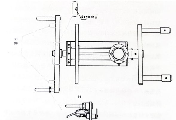
Sling
5. Spreader part:
The information part is composed of a communication control device and a horizontal Mo turning device. Rao Bao an get frame composition. Through the through-control dyeing, the ladle can be controlled to move up and down to the artificial building, and the handbrake can be squeezed to rotate. The horizontal rotating device enables the operator to apply easily. The ladle mounting frame should be connected with the ladle.
Packaging, transportation, installation and commissioning
1. Packaging, transportation and assembly
When shipping, the whole machine is fixed on the special transport bottom frame, and the balanced four-bar linkage is fixed on the fuselage with a fixed plate, so that it can not slide back and forth. Then use foamed plastic film to pack the fuselage, boom, motor, etc., to prevent surface paint damage and electricity
Parts of the equipment and fuel tank were wet with rain. The whole machine can also be divided into three parts: fuselage, balanced four-bar linkage mechanism and counterweight components for packing and transportation. Parts assembly machine according to the chart, put off guard and vertical guide plates, after the crane in arms above, to balance four bar linkage, the actuating arm, parallel to the arm support plate bearing on either side of the cross on the arm on the level of the upper guide, the guide wheel on the four connecting rod and the piston rod joint connection, two guide wheel installed in the middle of the vertical guide plate before and after, Then assembled according to the sample in turn guide shaft, the fixed vertical guide plate, plate, then balance beam fixed on the front axle and the big arm guide shaft, mount counterweight wheels, push LaDiao actuating arm can move horizontally, finally take the turn at the bottom of the lower limit of a piece of nail, the plug of the bottom of the four bar linkage and arm plug connection at the top of the well.
2. Installation and commissioning
Please read the instruction carefully before installing the machine. During installation, calibrate the level of the concrete foundation plane, and then fix the whole machine on the foundation. Pull the spreader to the maximum working radius at the same height and make a circular movement of 340 degrees. Find the horizontal point of the spreader at the third equal point, and the horizontal error of the three points shall not exceed 15mm. Connect to three-phase 380V, 50HZ working power supply (three-phase four-wire), the neutral line should be securely connected. After the check is correct, close the power switch of the electrical box, press the button to check whether the rotation direction of the motor is consistent with the marked direction, and then press the up or down button for debugging and operation according to the work needs. When stop working, should cut off the power switch.
Pay attention to safety matters
1. Before the power is introduced into the machine, three leakage protection switches should be installed.
2, the shell of the machine must be grounded (PE line), and the grounding is good.
3. Before opening the electrical box cover for maintenance, the external power supply must be cut off first.
4. When operating in the open air, rainproof and dustproof measures should be taken. It is strictly prohibited for rain to wet electrical appliances or rain to enter the tank.
5, remote transmitter should be two months (depending on the use) to replace the battery.
lubrication
1. The rolling bearings of each part of the machine are lubricated by calcium grease, cleaned and replaced once every six months.
2. The contact surface between front and rear vertical guide rail and roller is lubricated with calcium grease once a month.
3, the oil tank with 32#~48# anti-wear hydraulic oil, the oil surface should not be at the bottom of the oil window oil surface line 10mm below, the hydraulic oil model according to the use of the environment, cleaning every six months, replace once.
FIG. 2 Electrical schematic diagram
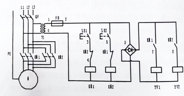
Table 2:
NO. | Code | Name | Specifications | Quantity | Remark |
1 | M | Motor | Shown in table 1 | 1 | |
2 | QF | Air Switch | DZ47-60-D16 | 1 | |
3 | U | Rectifier | KBPC30-10 | 1 | |
4 | SB1、SB2、SB3、SB4 | Remote Control | XJ-E2 TX | 1 | AC 24V |
5 | KM1、KM2 | AC contactor | CJX1-9 | 2 | AC 24V |
6 | YV1、YV2 | Magnetic Exchange Valve | DSG-02 3C60-D24 | 2 | AC 24V |
7 | TC | Control Transformer
| BK-50 380V/24V | 1 |
Figure 5
Schematic of hydraulic system
- PREV: BZ.A Jib crane

